First published on the Xianzhi community:https://xz.aliyun.com/t/6603
0x01 S7COMM Protocol
S7COMM stands for S7 Communication. It is Siemens' proprietary protocol for programming and exchanging data between S7-300/400 PLCs. S7 is carried over TPKT and ISO-COTP; this article focuses only on S7Comm. S7Comm contains three parts:[1][2][3][4][5][6][7]
- Header
- Parameter
- Data The Header contains eight fields, shown below:

Bytes 0–1:
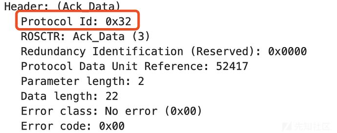
Protocol ID, normally 0x32;
Bytes 1–2:
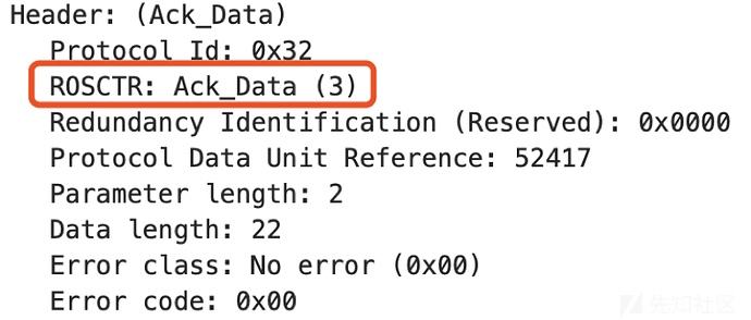
ROSCTR, or PDU type, generally has the following values:
- 0x01: JOB A job request, such as reading or writing memory or blocks, starting or stopping a device, or setting up communication
- 0x02: ACK A simple acknowledgment with no data
- 0x03: ACK_DATA Acknowledgment with data, normally a response to a Job request
- 0x07: USERDATA Extended protocol whose parameters include request and response IDs, commonly used for programming, debugging, and reading SZL data
Bytes 2–4:
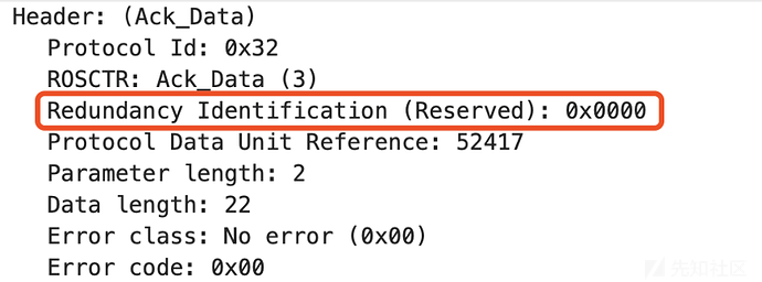
Redundancy Identification, reserved data normally 0x0000;
Bytes 4–6:
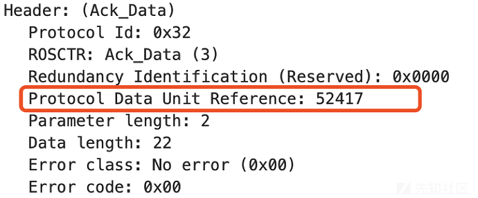
Protocol Data Unit Reference, incremented for each request event;
Bytes 6–8:
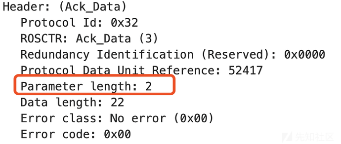
Parameter length: total length of the parameters
Bytes 8–10:
Data length: 0x0000 when reading internal PLC data; for other functions it is the length of the Data section;
Bytes 10–12:
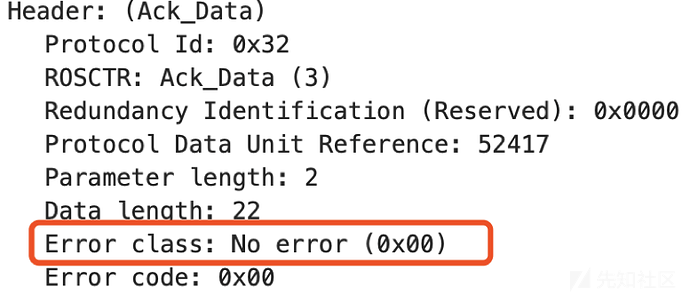
Error class: the meanings of its error codes appear in the following table:
| Hex | Value | Description |
|---|---|---|
| 0x00 | No error | No error |
| 0x81 | Application relationship | Application Relation |
| 0x82 | Object definition | Object definition |
| 0x83 | No resources available | No resources available |
| 0x84 | Error on service processing | Error processing service |
| 0x85 | Error on supplies | Request error |
| 0x87 | Access error | Access error |
Bytes 12–14:
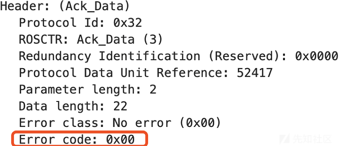
Error code; see for its meaningAppendix I: Error-Code Meanings
This completes the header. S7Comm Parameter and Data vary according to the PDU-type function code and protocol extensions in UserData. This article briefly introduces the PDU function codes and leaves the more complex extensions unexplained.
Common function codes for Job and ACK_DATA PDUs appear in the following table:
| Hex | Value | Meaning |
|---|---|---|
| 0x00 | CPU services | CPU service |
| 0xf0 | Setup communication | Establish communication |
| 0x04 | Read Var | Read value |
| 0x05 | Write Var | Write value |
| 0x1a | Request download | Request download |
| 0x1b | Download block | Download block |
| 0x1c | Download ended | End download |
| 0x1d | Start upload | Start upload |
| 0x1e | Upload | Upload |
| 0x1f | End upload | End upload |
| 0x28 | PI-Service | Program Invocation Service |
| 0x29 | PLC Stop | Stop PLC |
The following briefly introduces the structures of these function codes.
Setup communication(0xf0)
Setup Communication is sent at the start of every session before other messages. It negotiates the ACK queue size and maximum PDU length; both sides declare supported values, similar to maximum transmission units in networking. The queue length determines how many parallel jobs may start without acknowledgment. PDU and queue-length fields use big-endian order.
The Setup Communication Parameter structure is:
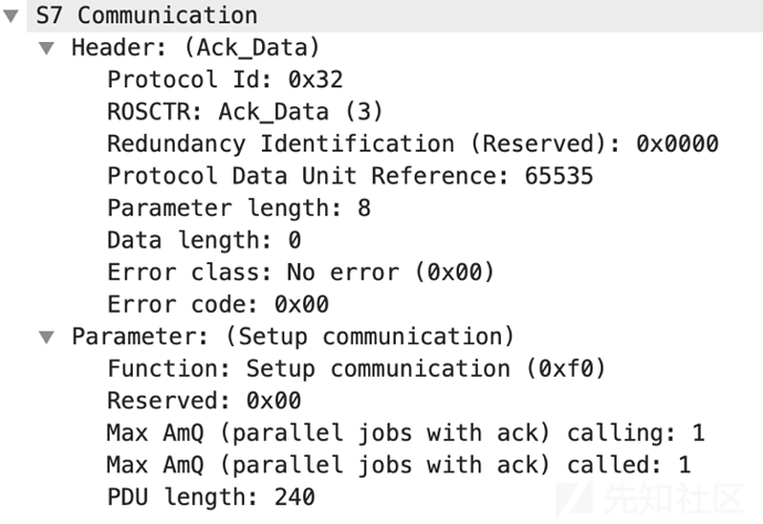

Bytes 0–1:
Function: Setup communication (0xf0) — the function declaration of Parameter/data.
Bytes 1–2:
Reserved: 0x00 — a reserved byte, normally 0x00.
Bytes 2–4:
Max AmQ (parallel jobs with ack) calling
Bytes 4–6:
Max AmQ (parallel jobs with ack) called
Bytes 6–8:
PDU length — the negotiated PDU length.
The following shows example Job and Ack_Data PDUs
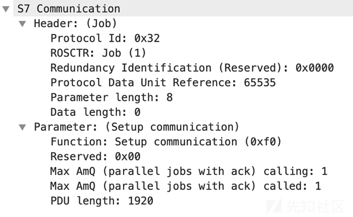
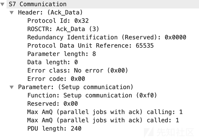
The negotiation above produces an ACK queue size of 1 and a maximum PDU length of 240.
Read Var(0x04)
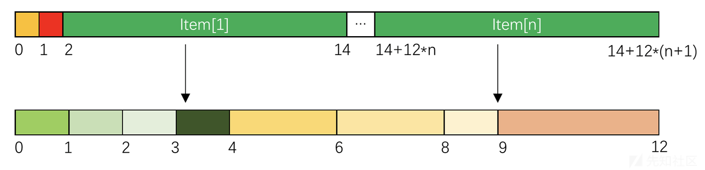
Read Var reads data by specifying a variable's memory area, address or offset, and size or type. Its Parameter and Item structures are:
Bytes 0–1:
Function: Read Var (0x04), the function declaration for Parameter/Data
Bytes 1–2:
Item count — the number of Items.
Bytes 2–14:
Item [1] — the first Item.
14+12n – 14+12Byte n+1:
Item[n] — the Nth Item.
One Item has the following structure:
Bytes 0–1:
Variable specification — the structure identifier, normally 0x12, meaning a variable specification.
Bytes 1–2:
Length of following address specification — the length of the address specification that follows this field.
Bytes 2–3:
Syntax Id, in full "Syntax Ids of variable specification" — the format type of the IDS address specification, which determines the addressing mode and the layout of the rest of the item. Common variable structure identifiers are listed below:
| Hex | Value | Description |
|---|---|---|
| 0x10 | S7ANY | Address data S7-Any pointer-like DB1.DBX10.2 |
| 0x13 | PBC-R_ID | R_ID for PBC |
| 0x15 | ALARM_LOCKFREE | Alarm lock/free dataset |
| 0x16 | ALARM_IND | Alarm indication dataset |
| 0x19 | ALARM_ACK | Alarm acknowledge message dataset |
| 0x1a | ALARM_QUERYREQ | Alarm query request dataset |
| 0x1c | NOTIFY_IND | Notify indication dataset |
| 0xa2 | DRIVEESANY | seen on Drive ES Starter with routing over S7 |
| 0xb2 | 1200SYM | Symbolic address mode of S7-1200 |
| 0xb0 | DBREAD | Kind of DB block read, seen only at an S7-400 |
| 0x82 | NCK | Sinumerik NCK HMI access |
Bytes 3–4:
Transport size — the transport size of the data. Common values are listed below:
| Hex | Value | Description |
|---|---|---|
| 0 | NULL | |
| 3 | BIT | bit access, len is in bits |
| 4 | BYTE/WORD/DWORD | byte/word/dword access, len is in bits |
| 5 | INTEGER | integer access, len is in bits |
| 6 | DINTEGER | integer access, len is in bytes |
| 7 | REAL | real access, len is in bytes |
| 9 | OCTET STRING | octet string, len is in bytes |
Bytes 4–6:
Length — the length of the data.
Bytes 6–8:
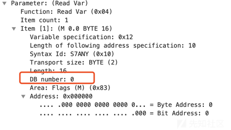
DB number — the DB number. If the access does not target a DB area this field is 0x0000, as shown below:
Bytes 8–9:
Area — the memory area. Common areas are listed below:
| Hex | Value | Description |
|---|---|---|
| 0x03 | System info of 200 family | S7-200 system information |
| 0x05 | System flags of 200 family | S7-200 system flags |
| 0x06 | Analog inputs of 200 family | S7-200 analog inputs |
| 0x07 | Analog outputs of 200 family | S7-200 analog outputs |
| 0x80 | Direct peripheral access (P) | Direct peripheral access |
| 0x81 | Inputs (I) | Input (I) |
| 0x82 | Outputs (Q) | Output (Q) |
| 0x83 | Flags (M) | Internal flags (M) |
| 0x84 | Data blocks (DB) | Data block (DB) |
| 0x85 | Instance data blocks (DI) | Instance data block (DI) |
| 0x86 | Local data (L) | Local variables (L) |
| 0x87 | Unknown yet (V) | Global variables (V) |
| 0x1c | S7 counters (C) | S7 counter (C) |
| 0x1d | S7 timers (T) | S7 timer (T) |
| 0x1e | IEC counters (200 family) | IEC counter, S7-200 series |
| 0x1f | IEC timers (200 family) | IEC timer, S7-200 series |
Bytes 9–12:
Address — the address.
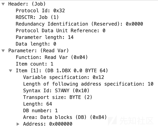
A simple example shows the core content of an Item packet:
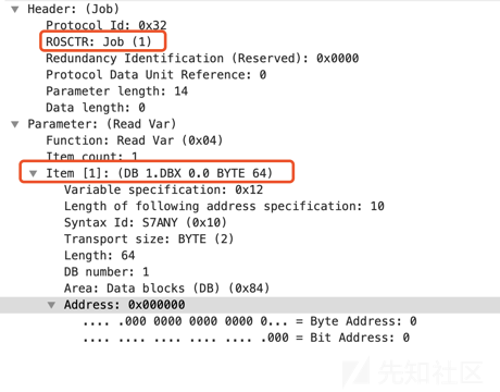
This is a Job PDU with the Read Var function. Item[1] reads a BYTE from DB1 at address 0x00000000.
For Read Var, the Ack_Data Parameter structure differs from the Job Parameter structure, as shown below:
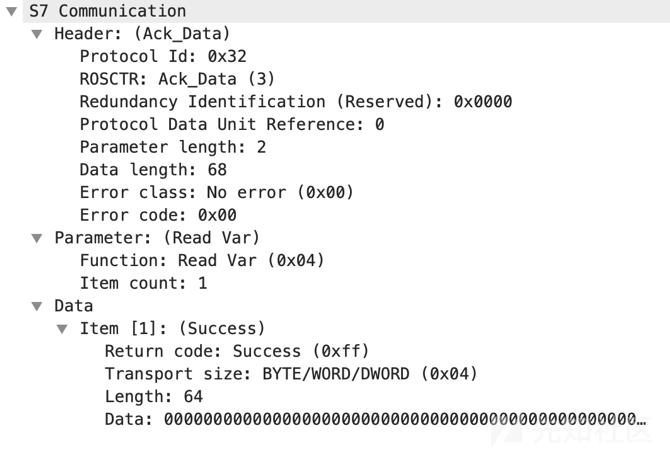
Its Parameter contains only function and item count, but the response also includes Data, which is absent from a Job PDU. The Data structure is shown below:

Bytes 0–1:
Return code — the return code. Common return codes in the Data part of a response are listed below:
| Hex | Value | Description |
|---|---|---|
| 0x00 | Reserved | Undefined; reserved |
| 0x01 | Hardware error | Hardware error |
| 0x03 | Accessing the object not allowed | Object access not permitted |
| 0x05 | Invalid address | Invalid address: requested address exceeds this PLC's limits |
| 0x06 | Data type not supported | Data type not supported |
| 0x07 | Data type inconsistent | Date types do not match |
| 0x0a | Object does not exist | Object does not exist |
| 0xff | Success | Success |
Bytes 1–2:
Transport size — the transport size of the data. Common transport size values inside data are listed below:
| Hex | Value | Description |
|---|---|---|
| 0 | NULL | |
| 3 | BIT | bit access, len is in bits |
| 4 | BYTE/WORD/DWORD | byte/word/dword access, len is in bits |
| 5 | INTEGER | integer access, len is in bits |
| 6 | DINTEGER | integer access, len is in bytes |
| 7 | REAL | real access, len is in bytes |
| 9 | OCTET STRING | octet string, len is in bytes |
Bytes 2–4:
Length: — the length of the data.
Bytes 4 through 4+length, undefined:
Data — the data itself.
Bytes 4+length through 5, undefined:
Fill byte — padding. If the data length does not reach the Length given in bytes 2-4, it is padded with 0x00.
Write Var(0x05)
Write Var writes data by specifying a variable's memory area, address or offset, and size or type. Its Parameter structure matches Read Var, but it includes an additional Data structure for the values being written:
The Write Var structure is:
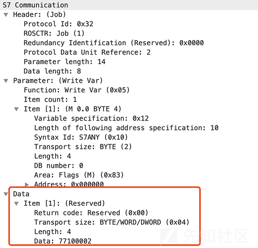
The diagram shows a Job request writing 0x77100002 to Flags (M) at address 0x000000. The corresponding Ack_Data structure is similar:
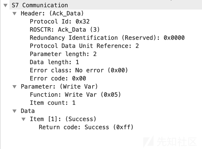
Compared with Read Var, Write Var Data has only a Return Code field. Item 1 indicates that 0x77100002 was successfully written to Flags (M) at address 0x000000.
Request download(0x1a)
Request Download begins a download. It is part of a complete flow with Download Block and Download Ended; together the three function codes form the full download process. The flow is:

With the overall flow established, we can examine Request Download. Its Parameter structure is:
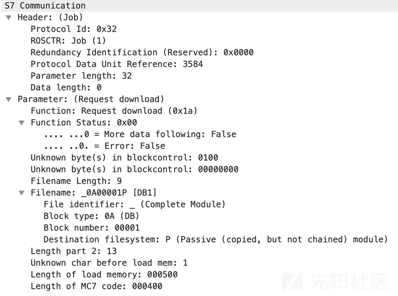

Bytes 0–1:
Function: Request download (0x1a) — the function declaration of Parameter/data.
Bytes 1–2:
Function Status — the function status: whether an error occurred, and whether more data is requested through another retrieval block/file.
Bytes 2–4:
Unknown byte(s) in blockcontrol — no meaning.
Bytes 4–8:
Unknown byte(s) in blockcontrol — no meaning, normally 0x00000000.
Bytes 8–9:
Filename Length — the length of the filename.
Bytes 9–18:
Filename — the filename. Its structure is:

Bytes 0–1:
File identifier — the file identifier. There are two: _ (Complete Module) and $ (Module header for up-loading).
Bytes 1–3:
Block type — the block type. Siemens devices have eight different function block types, listed below:
| Hex | Type | Description |
|---|---|---|
| 0x3038 | OB, ASCII '08': organization block | OBs determine the structure of the user program |
| 0x3039 | CMod, ASCII '09' | |
| 0x3041 | DB, ASCII '0A': data block | A DB is a data area for user data. Besides data assigned to a function block, it can hold shared data usable by any block. |
| 0x3042 | SDB, ASCII '0B': system data block | Generated automatically by programming software, primarily storing PLC hardware configuration; users cannot open or modify it directly |
| 0x3043 | FC, ASCII '0C': function | FB and FC are both subroutines callable by other programs and able to call other subroutines. An FC uses shared data blocks. |
| 0x3044 | SFC, ASCII '0D': system function | SFBs and SFCs are built into S7 CPUs and expose important system functions |
| 0x3045 | FB, ASCII '0E': function block with an instance data block | FB and FC are both subroutines that can be called by other programs and can call other subroutines. An FB uses an instance data block. |
| 0x3046 | SFB, ASCII '0F': system function block | SFBs and SFCs are built into S7 CPUs and expose important system functions |
| OB, FB, SFB, FC, and SFC all contain program code and are therefore called logic blocks. The permitted number and length of each block type depend on the CPU. |
Bytes 3–8:
Block number: number of the requested block
Bytes 8–9:
Destination filesystem — the target filesystem of the request. There are three:
- P, Passive copied but not chained module: passive file system
- A, Active embedded module: active file system
- B, active as well as passive module: both active and passive file system
Bytes 18–19:
Length part — the length of the second part of the parameter, that is, the length of the fields that follow.
Bytes 19–20:
Unknown char before load mem — the unknown character preceding the load memory field.
Bytes 20–26:
Length of load memory — the load length.
Bytes 26–32:
Length of MC7 code — the length of the MC7 code.
This is the Request Download structure. It tells the PLC that a block download is about to begin, as in the following example:
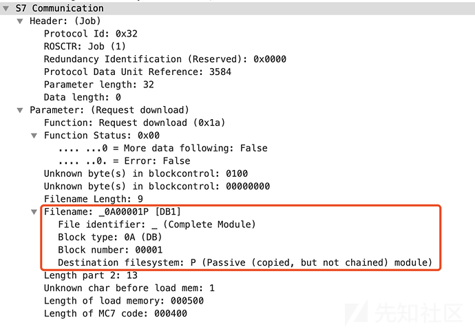
In the diagram, the requested file identifier is _ for Complete Module, the block type is DB, the block number is 00001, and the target file system is P for Passive module. The filename is therefore _0A00001P, used to copy DB1 to or from the passive file system.
As with file reads and writes, the request uses a Job PDU. For Ack_Data, the Request Download structure is:
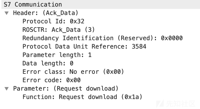
Its Parameter contains only a function acknowledgment. After the Request Download Job and Ack_Data complete, Download Block can begin.
Download block(0x1b)
The Download Block Parameter structure is:
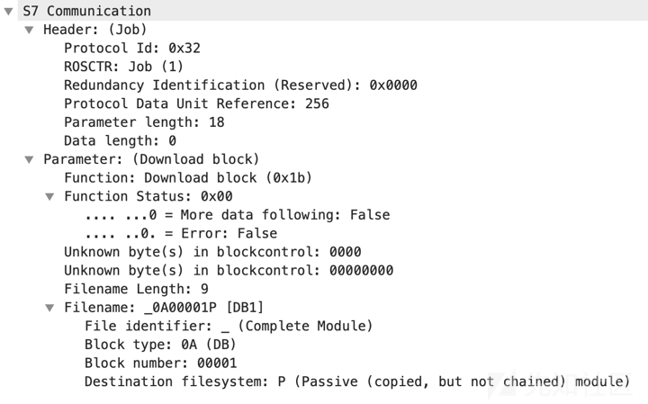
We can see thatDownload blockofParametercontent is the same asrequest downloadoverlaps with the content of, but lacks bytes 18–32 compared with the latter(Length part、Unknown char before load mem、Length of load memory、Length of MC7 code); the diagram above is the download block _0A00001P job request.
For an Ack_Data PDU, the Parameter structure is shown below:
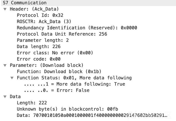
Parameter contains only the function acknowledgment and status, while the additional Data structure contains the data length, unknown bytes, the data content, and its length.
A complete block download may require several requests, as shown below:

Download ended(0x1c)
The Download Ended Parameter structure is:
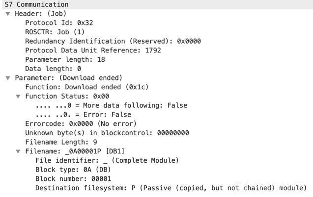
The preceding diagram showsDownload endedandDownload blockofParameterandRequest downloadofParametermatches the first part of, but lacks bytes 18–32(Length part、Unknown char before load mem、Length of load memory、Length of MC7 code), meaning that the download has ended0A00001Pjob request.
For Ack_Data, the Download Ended Parameter structure is:
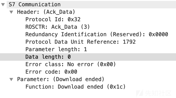
The response contains only a function acknowledgment, confirming the end of the _0A00001P download and completing the process.
Start upload(0x1d)
Start Upload begins an upload and is similar to Request Download. It must be understood as part of the complete upload flow: Start Upload, Upload, and End Upload together form one upload session.
The flow is:
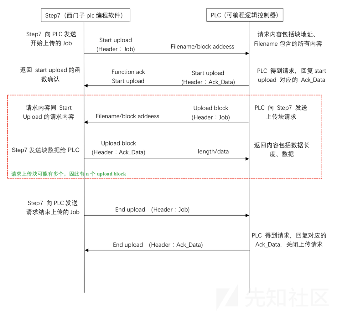
With the overall flow established, we can examine Start Upload. Its Parameter structure is:
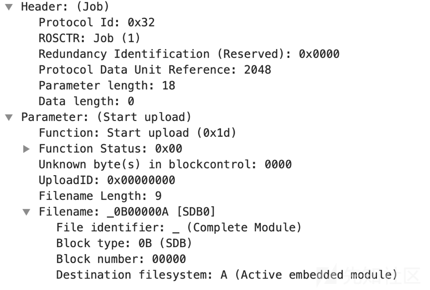
We can see thatStart upload structure andRequest Download has the same initial structure. The content above tells the PLC a filename whose identifier is _ (Complete Module), and the block type is0B(SDB), and the block number is00000, and the target block's file system isA (Active embedded module), so the filename is_0B00000A
For an Ack_Data PDU, the structure is shown below:
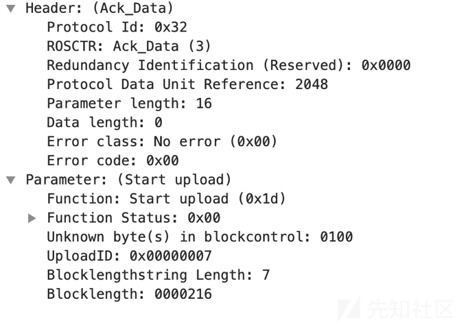

Bytes 0–1:
Function: Start upload (0x1d) — the function declaration of Parameter/data.
Bytes 1–2:
Function Status — the function status: whether an error occurred, and whether the request goes through another retrieval block/file.
Bytes 2–4:
Unknown byte(s) in blockcontrol — all the unknown bytes inside blockcontrol.
Bytes 4–8:
UploadID — the ID of the file upload session.
Bytes 8–9:
Blocklengthstring Length — the byte length that follows the block length string.
Bytes 9–16:
Blocklength — the length of the complete upload block in bytes; it may be split across several PDUs.
Upload(0x1e)
When the PDU type is Job, Upload contains no Data. Its Parameter structure is shown below:
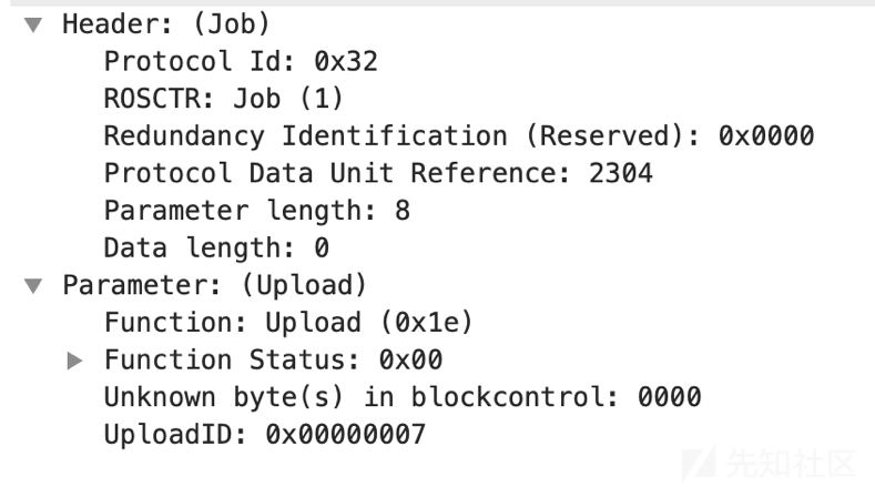

Bytes 0–1:
Function: Upload (0x1E), function-code status;
Bytes 1–2:
Function Status — the function status: whether an error occurred, and whether the request goes through another retrieval block/file.
Bytes 2–4:
Unknown bytes in blockcontrol: all unidentified blockcontrol bytes
Bytes 4–8:
UploadID — the upload session ID, which tells Step7 which upload session this is.

That is the JOB-type structure. When the PDU type is Ack_Data, Upload carries Data, and its Parameter is structured as follows:
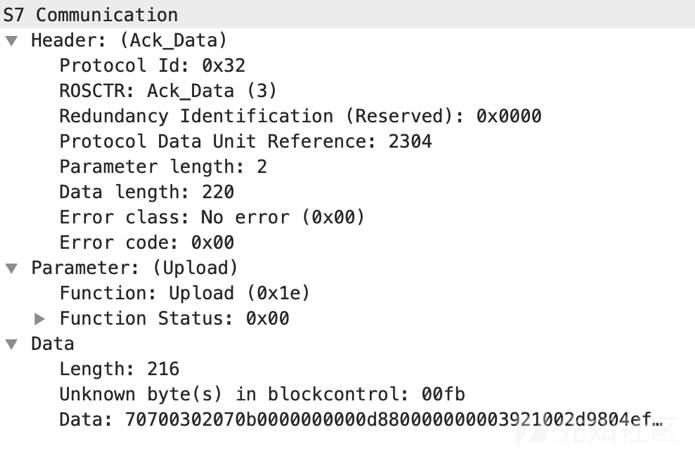
Parameter contains only the function acknowledgment and status. The byte count in the additional Data depends on its data length. This structure matches Download Block.
End upload(0x1f)
At the end of an upload session, after all blocks have been uploaded, STEP 7 sends an End Upload Job. The PLC closes the session and returns an Ack_Data response.
The End Upload Parameter structure is:
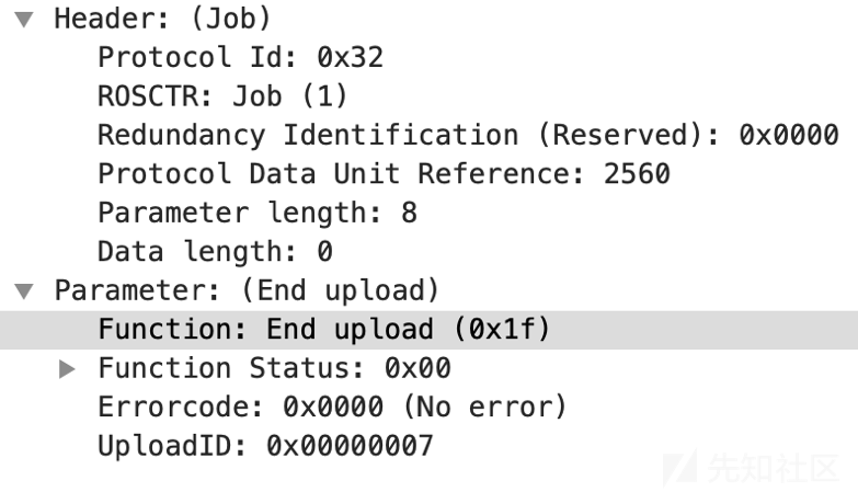
The structure is simple: eight bytes total, with UploadID the largest field at four bytes.
When the PDU type is Ack_Data, its structure is:
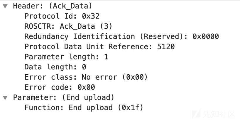
The structure contains only a function acknowledgment. This completes the upload process.
PI-Service(0x28)
PI-Service means Program Invocation Service. It supports routine PLC changes to execution and memory state, including starting or stopping the control program and activating or deleting program blocks.
The PI-Service Parameter structure is:
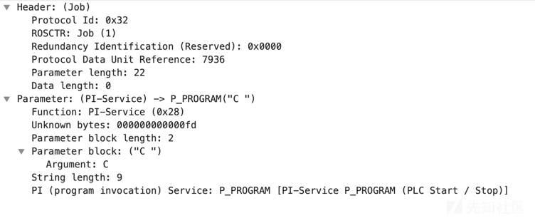

Bytes 0–1:
Function: PI-Service (0x28) — the function code status.
Bytes 1–8:
Unknown bytes — unknown bytes.
Bytes 8–10:
Parameter block length — the length of the parameter block.
Bytes 10–12:
Parameter block — the parameter block.
Bytes 12–13:
String length — the string length of the PI service.
Bytes 13–22:
PI (program invocation) Service — the program invocation service name; see Appendix 2 for details.
If a service-call parameter is a block, the Parameter Block structure differs, as shown below:
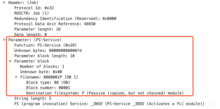
The principal meanings in the diagram are:
Service name: _INSE Parameter: 0800001P [OB 1] Request: activate OB 1
The request result is shown below:
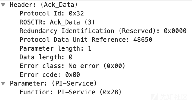
Function acknowledged; request succeeded
PLC Stop(0x29)
PLC STOP is essentially the same as PI-Service. Its Parameter structure is:
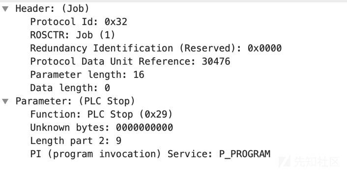
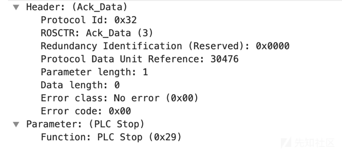
The main difference from PI-Service is that PLC Stop has no Parameter Block structure. Other structures, including Ack_Data, are the same:
Summary
The preceding sections introduced Job and ACK_DATA PDUs in S7Comm. The more complex UserData format is omitted because of its breadth and complexity; interested readers can consult other material. This is only an introduction to Job and ACK_DATA. UserData supports many operations, such asTIME functions、NC programming、CPU functions、Cyclic data、Securityand related values.
0x02 MODBUS Protocol
Modbus was introduced by Modicon, producing Modbus RTU and Modbus ASCII. Schneider Electric later(SchneiderElectric)acquired Modicon and introduced Modbus TCP in 1997.
In 2004, China's National Standardization Administration formally adopted Modbus as a national standard, beginning its contribution to Chinese industrial communication.
MODBUS is an application-layer messaging protocol at layer 7 of the OSI model, providing client/server communication between devices on different buses or networks. Since 1979, it has remained an industry standard that enables millions of automation devices to communicate.
MODBUS is a request/reply protocol providing services identified by function codes. A MODBUS function code is an element of the request or response PDU. This article does not cover transport, error detection, or the physical layer; it only introduces common function codes.
MODBUS function codes fall into valid, exception, and error codes. There are more than twenty valid codes, but common use primarily centers on1、2、3、4、5、6、15、16are the eight most commonly used, plus the special function codes 20 and 21 for General Reference Registers, which most Modbus devices do not provide.
I originally planned to cover MODBUS in depth, but the official documentation already does so, so I will not repeat it here.
Documentation download: see the link at the end English version:

Chinese version
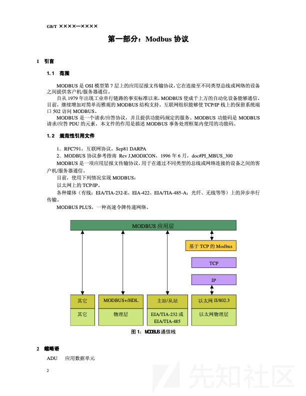
This document explains Modbus function codes and their operation in detail. Interested readers can download and study it.
0x03 Example Analysis
Example 1: S7Comm Protocol Analysis
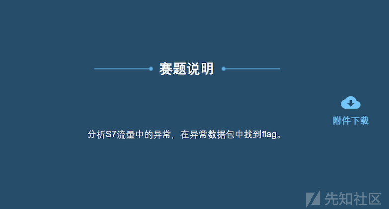
Challenge Description
Analyze anomalies in S7 traffic and find the flag in a malformed packet.
Solution
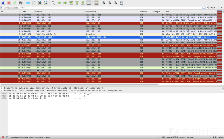
Open the file as shown below:
Because the challenge specifies S7, non-S7 traffic can be excluded:
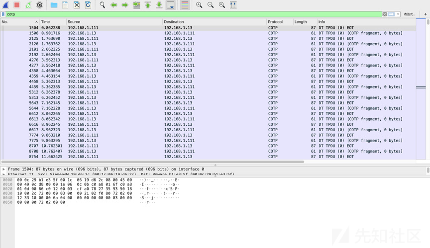
There are too many packets to identify the PDU types directly, so export the group:

Use the following script to identify PDU types and counts:
#!/usr/bin/env python
#encoding=utf-8

import pyshark

captures = pyshark.FileCapture("cotp.pcapng")
pdu_types = {}
for c in captures:
    for pkt in c:
        if pkt.layer_name == "cotp":
            if hasattr(pkt, "type"):
                type = pkt.type
                if type in pdu_types:
                    pdu_types[type] += 1
                else:
                    pdu_types[type] = 1
print(pdu_types)
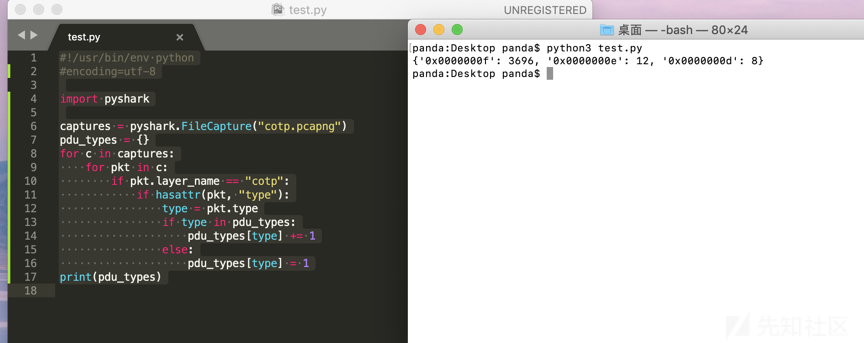
Three PDU function codes are present: 0x0F 3,696 times, 0x0E 12 times, and 0x0D 8 times.
COTP was not introduced above, but the difference is largely one of function and transport format. The three function codes are:
PDU Type: DT Data (0x0f):
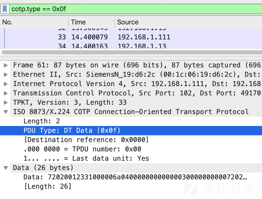
Primarily used for data transfer; Parameter includes a Data structure
PDU Type: CR Connect Request (0x0e)
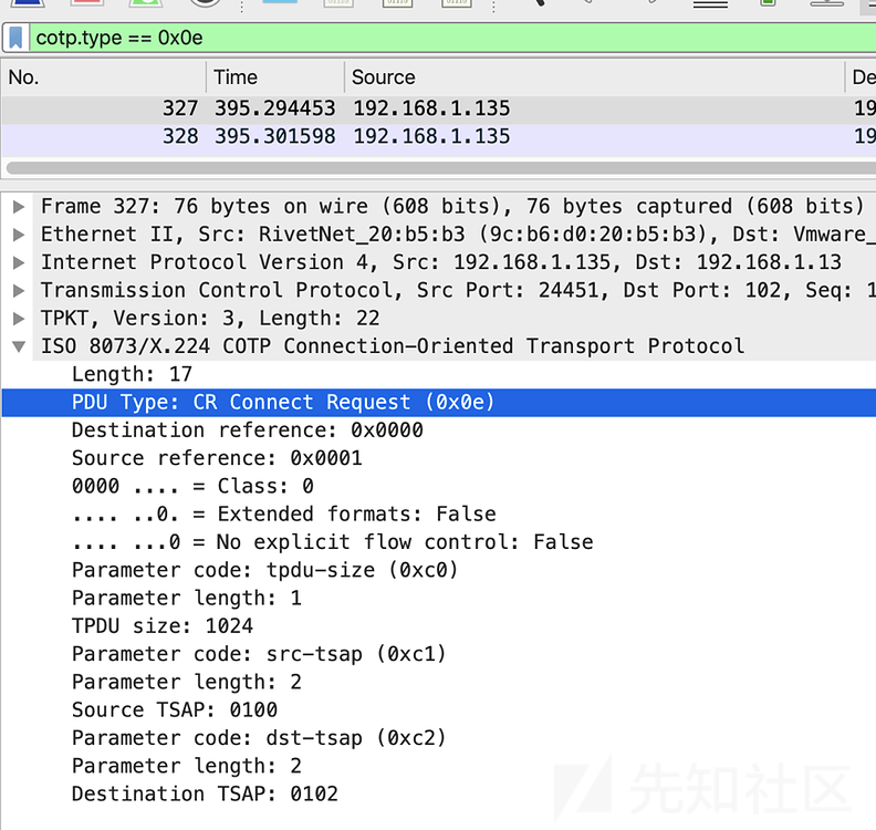
Primarily used to initiate a connection request
PDU Type: CC Connect Confirm (0x0d)
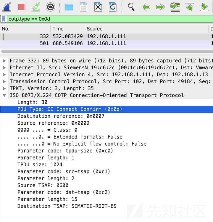
Primarily used to acknowledge a connection
By frequency, function codes 0x0D and 0x0E are most likely to contain the flag, so analyze those two:
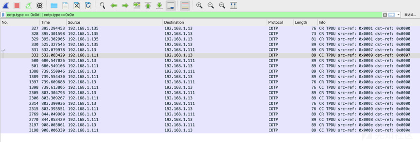
Notice:
Each connection request has a corresponding acknowledgment. The first three packets contain three consecutive requests, which is suspicious. Inspection shows:
The third packet contains meaningful data: NESSUS
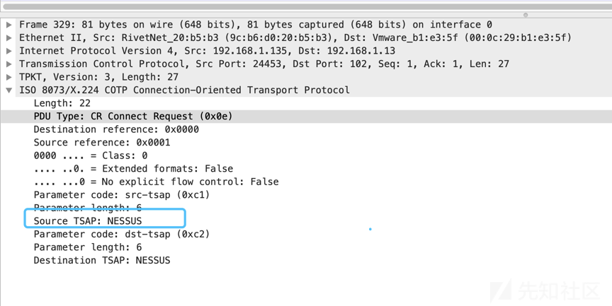
No other packet contained meaningful data, so this string is the flag.
Example 2: Modbus Protocol Analysis
Challenge Description
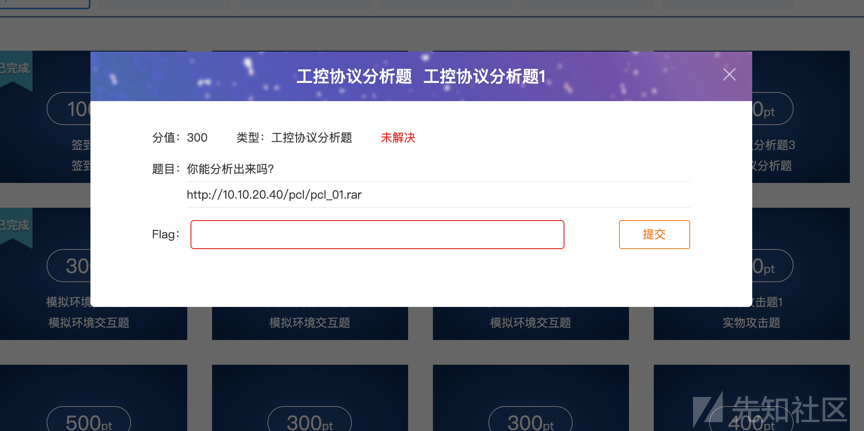
No hints were provided; this was simply a protocol-analysis challenge.
Solution
Opening the file reveals:
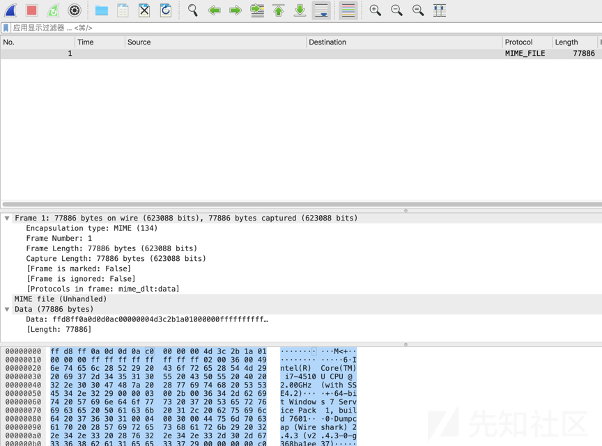
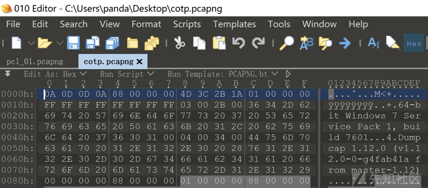
The packet is malformed. Comparing it with a normal packet shows that its header and footer were altered, so use 010 Editor to repair them:
Normal pcap packet
Download the pcap file:
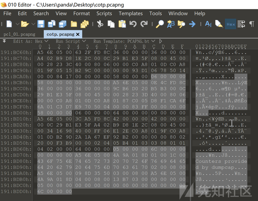
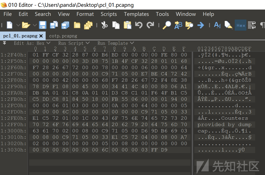
Remove the first three and last three bytes, then open the modified file:
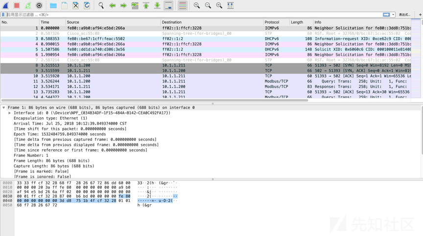
The capture contains many protocols, but this article focuses only on Modbus—the flag is also in Modbus. Filter and export the Modbus packets by group, then use the following script to identify the function codes present:
#!/usr/bin/env python
#encoding=utf-8

import pyshark

captures = pyshark.FileCapture("modbus-ics.pcapng")
modbus_func_code = {}
for c in captures:
    for modbus in c:
        if modbus.layer_name == "modbus":
            if hasattr(modbus, "func_code"):
                type = modbus.func_code
                if type in modbus_func_code:
                    modbus_func_code[type] += 1
                else:
                    modbus_func_code[type] = 1
print(modbus_func_code)

Only function code 3 appears, in 274 packets.
As noted earlier, the Modbus protocol uses1、2、3、4、5、6、15、16are the eight most commonly used.
The following table briefly describes Modbus function codes:
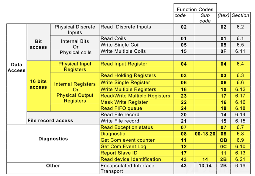
Function code 3 reads registers, so finding the register content reveals the flag. Inspect the traffic:

Only register 1 changes continuously. Extract its values in transmission order and convert them to ASCII to obtain:
0x39,0x65,0x32,0x33,0x32,0x61,0x62,0x39,0x65,0x30,0x63,0x32,0x65,0x31,0x37,0x33,0x35,0x39,0x64,0x37,0x61,0x64,0x37,0x61,0x64,0x65,0x61,0x30,0x61,0x33,0x30,0x37,0x31,0x38,0x65,0x00,0x33,0x35,0x32,0x66,0x63,0x36,0x31,0x31,0x33,0x66,0x64,0x62,0x61,0x33,0x32,0x36,0x64,0x34,0x39,0x38,0x37,0x37,0x63,0x37,0x33,0x38,0x33,0x34,0x35,0x34,0x65,0x37,0x00,0x61,0x65,0x62,0x66,0x62,0x61,0x34,0x35,0x32,0x33,0x63,0x64,0x66,0x30,0x33,0x64,0x64,0x66,0x65,0x38,0x65,0x66,0x38,0x64,0x66,0x36,0x32,0x30,0x66,0x66,0x35,0x30,0x00,0x61,0x33,0x64,0x65,0x62,0x39,0x65,0x65,0x32,0x37,0x32,0x35,0x37,0x36,0x33,0x33,0x66,0x35,0x39,0x30,0x35,0x37,0x63,0x35,0x36,0x35,0x34,0x64,0x66,0x66,0x65,0x36
Use the following script to convert it to a string:
#!/usr/bin/env python
#encoding=utf-8
data = 0x39,0x65,0x32,0x33,0x32,0x61,0x62,0x39,0x65,0x30,0x63,0x32,0x65,0x31,0x37,0x33,0x35,0x39,0x64,0x37,0x61,0x64,0x37,0x61,0x64,0x65,0x61,0x30,0x61,0x33,0x30,0x37,0x31,0x38,0x65,0x00,0x33,0x35,0x32,0x66,0x63,0x36,0x31,0x31,0x33,0x66,0x64,0x62,0x61,0x33,0x32,0x36,0x64,0x34,0x39,0x38,0x37,0x37,0x63,0x37,0x33,0x38,0x33,0x34,0x35,0x34,0x65,0x37,0x00,0x61,0x65,0x62,0x66,0x62,0x61,0x34,0x35,0x32,0x33,0x63,0x64,0x66,0x30,0x33,0x64,0x64,0x66,0x65,0x38,0x65,0x66,0x38,0x64,0x66,0x36,0x32,0x30,0x66,0x66,0x35,0x30,0x00,0x61,0x33,0x64,0x65,0x62,0x39,0x65,0x65,0x32,0x37,0x32,0x35,0x37,0x36,0x33,0x33,0x66,0x35,0x39,0x30,0x35,0x37,0x63,0x35,0x36,0x35,0x34,0x64,0x66,0x66,0x65,0x36

ret=''
for i in data:
    if i == 0:
        ret+='\n'
    else:
        ret += chr(i)

print (ret)
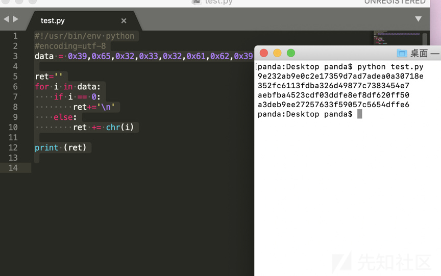
This produces four lines of text:
9e232ab9e0c2e17359d7ad7adea0a30718e
352fc6113fdba326d49877c7383454e7
aebfba4523cdf03ddfe8ef8df620ff50
a3deb9ee27257633f59057c5654dffe6
The final three strings can be cracked directly as MD5 values:_love_this_game!
The first value has three extra characters. Positions 19 through 24 are duplicated, so remove the duplicate.d7a; cracking the MD5 values givespcl_i
The final flag is pcl_i_love_this_game!
Example 3: Industrial-Control System Operation 1
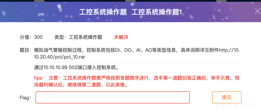
Requirement
- Adjust a valve opening from 35 to above 60 and keep it stable for more than three seconds.
- Completion time: 30 minutes
Known Conditions
- IP address of the industrial-control device or virtual machine.
- The device supports Modbus on port 502
- The PLC exposes the following registers and coils:
- Status registers
0x0000~0x0009, used for monitoring. - Control registers
0x000A~0x0014, used for control. - Status coils
0x0000~0x0009, used for monitoring. - Control coils
0x000A~0x0014, used for control. - Additional registers
0x1000~0x1063, used to submit the flag.
- The valve opening uses status register 0x0008 and control register 0x0010.
Completion criterion
After success, registers 0x1000–0x1007 automatically contain eight nonzero values. Their ASCII representation is the flag.
Solution
The original environment is no longer available, so only a brief explanation is possible.
Nobody solved this challenge for a long time, so the organizers eventually provided a hint:
- One prerequisite for setting the value is that the system be in maintenance mode
- Control register 0x000B stores the operating mode: 3 means maintenance and 0 means run.
- To prevent accidental operation, the working mode is locked during normal runtime. Changing it first requires unlocking through a control coil.
The hint requires entering system maintenance mode. Testing showed that only coil 15 can be changed, so write Boolean true to coil 15, change operating mode from 11 to 3, then write 100 to controller address 16—another value above 64 also works. Restore normal mode by setting coil 11 to 0 and controller 15 to false. ASCII can then be read from 4096[+10], as shown below:
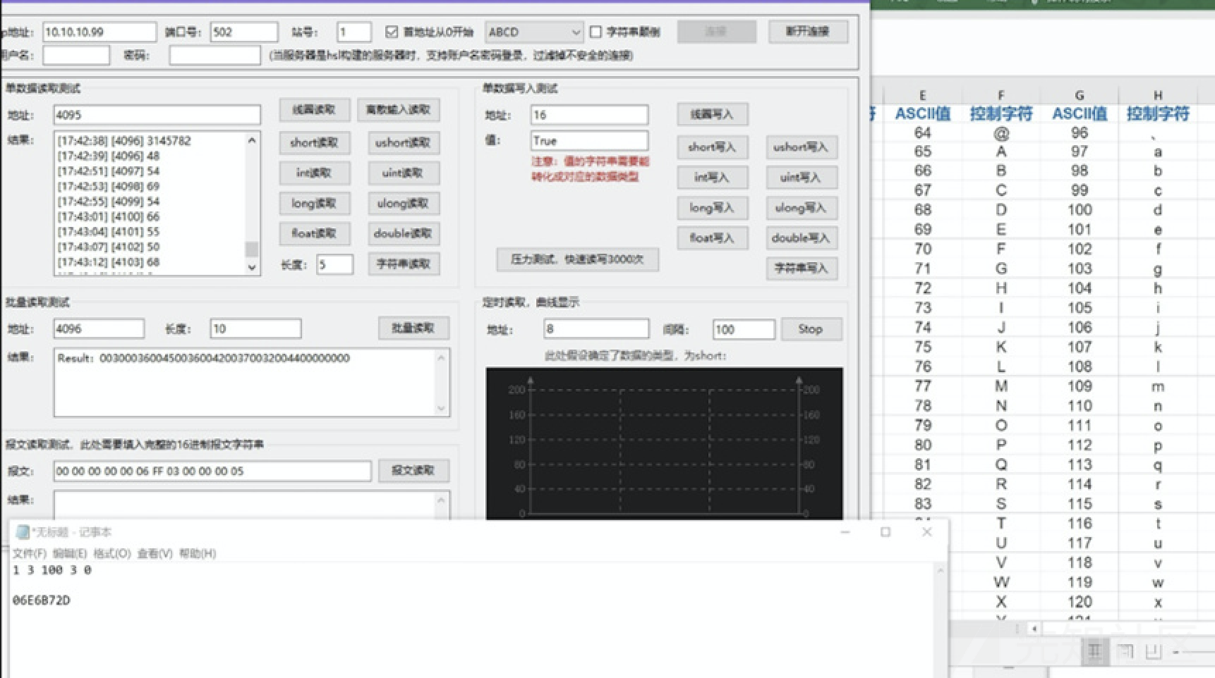
After conversion, the flag is 06E6B72D
Example 3: Industrial-Control System Operation 2
Requirement
- Enable the PLC alarm switch through normal communication;
- Read a PLC-generated log and determine the alarm time recorded in it.
- Completion time: 30 minutes.
Known Conditions
- IP address of the industrial-control device or virtual machine.
- The device supports Modbus on port 502.
- The PLC exposes the following registers and coils:
- Status registers
0x0000~0x0009, used for monitoring. - Control registers
0x000A~0x0014, used for control. - Status coils
0x0000~0x0009, used for monitoring. - Control coils
0x000A~0x0014, used for control. - Status registers
0x100~0x163, used for alarm logs.
- The control-coil address for the alarm-log enable switch is 0x000D
Completion criterion
After finding the alarm time, use it as the flag in the formatyyyy-mm-dd hh:mm:ss
Solution
This challenge builds on the preceding one. First enable logging by setting coil 13 to true. After fuzzing several registers, error values appeared at 256[+100], so read that address:
[18:25:10] [256] 25
[18:25:12] [257] 13
[18:25:16] [258] 84 T
[18:25:19] [259] 224
[18:25:23] [260] 92 /

[18:25:26] [261] 115 s
[18:25:29] [262] 119 w
[18:25:32] [263] 105 i
[18:25:34] [264] 116 t
[18:25:37] [265] 99 c
[18:25:39] [266] 104 h
[18:25:41] [267] 32 space
[18:25:44] [268] 49 1
[18:25:46] [269] 51 3
[18:25:50] [263] 105 i
[18:25:56] [270] 49 1
[18:25:59] [271] 32 space
[18:26:02] [272] 116 t
[18:26:06] [273] 114 r
[18:26:08] [274] 105 i
[18:26:10] [275] 112 p
[18:26:13] [276] 32 space
[18:26:15] [277] 111 o
[18:26:18] [278] 102 f
[18:26:20] [279] 102 f
[18:26:23] [280] 46 .
[18:26:26] [281] 0
[18:26:28] [282] 76 L
[18:26:33] [283] 0
[18:26:37] [284] 0
[18:26:39] [285] 0
Analysis of the preceding data shows190d54e05cPossibly a timestamp.
After splitting and reordering for endianness:5CE0540D, then convert to decimal 1558205453, converted to a Unix timestamp:

Submit flag: 2019-5-19 2:50:53
There was a third industrial-control challenge, but we ran out of time to calculate the checksum and did not obtain its flag, so it is omitted here.
0x04 Conclusion
S7 has no public official specification or standardized public terminology. My knowledge is limited, and this introductory article combines online material with my own understanding. Corrections are welcome. Industrial-control security also depends heavily on access to real, simulated, or emulated equipment. This article is only an introductory reference, and I hope it helps.
0x06 Appendix I: Error-Code Meanings
| Error code | Meaning |
|---|---|
| 0x0000 | No error |
| 0x0110 | Invalid block number |
| 0x0111 | Invalid request length |
| 0x0112 | Invalid parameter |
| 0x0113 | Invalid block type |
| 0x0114 | Block not found |
| 0x0115 | Block already exists |
| 0x0116 | Block is write-protected |
| 0x0117 | Block or operating-system update too large |
| 0x0118 | Invalid block number |
| 0x0119 | Incorrect password |
| 0x011A | PG resource error |
| 0x011B | PLC resource error |
| 0x011C | Protocol error |
| 0x011D | Too many blocks; module-specific limit |
| 0x011E | No longer connected to the database, or invalid S7DOS handle |
| 0x011F | Result buffer too small |
| 0x0120 | End-of-block list |
| 0x0140 | Insufficient available memory |
| 0x0141 | Cannot process the job because resources are unavailable |
| 0x8001 | Requested service cannot execute while the block is in its current state |
| 0x8003 | S7 protocol error while transferring a block |
| 0x8100 | Application general error: unknown service on the remote module |
| 0x8104 | Service not implemented on the module, or frame error reported |
| 0x8204 | Object type specifications do not match |
| 0x8205 | Copied block already exists and is not linked |
| 0x8301 | Insufficient module memory or work memory, or specified storage medium inaccessible |
| 0x8302 | Too few resources available, or processor resources unavailable |
| 0x8304 | No further parallel uploads possible; resource bottleneck |
| 0x8305 | Function unavailable |
| 0x8306 | Insufficient work memory for copying, linking, or loading AWP |
| 0x8307 | Insufficient retentive work memory for copying, linking, or loading AWP |
| 0x8401 | S7 protocol error: invalid service sequence, such as loading or uploading a block |
| 0x8402 | Service cannot execute because of the addressed object's state |
| 0x8404 | S7 protocol: function cannot be executed |
| 0x8405 | Remote block is DISABLED (CFB); function cannot execute |
| 0x8500 | S7 protocol error: frame error |
| 0x8503 | Alarm from module: service canceled prematurely |
| 0x8701 | Error addressing an object on the communication partner, such as invalid area length |
| 0x8702 | Module does not support the requested service |
| 0x8703 | Object access denied |
| 0x8704 | Access error: object damaged |
| 0xD001 | Protocol error: invalid job number |
| 0xD002 | Parameter error: invalid job variant |
| 0xD003 | Parameter error: module does not support the debugging function |
| 0xD004 | Parameter error: invalid job state |
| 0xD005 | Parameter error: invalid job termination |
| 0xD006 | Parameter error: invalid link-disconnect ID |
| 0xD007 | Parameter error: invalid number of buffer elements |
| 0xD008 | Parameter error: invalid scan rate |
| 0xD009 | Parameter error: invalid execution count |
| 0xD00A | Parameter error: invalid trigger event |
| 0xD00B | Parameter error: invalid trigger condition |
| 0xD011 | Parameter error in call-environment path: block does not exist |
| 0xD012 | Parameter error: invalid address in block |
| 0xD014 | Parameter error: block is being deleted or overwritten |
| 0xD015 | Parameter error: invalid tag address |
| 0xD016 | Parameter error: job cannot be tested because of an error in the user program |
| 0xD017 | Parameter error: invalid trigger number |
| 0xD025 | Parameter error: invalid path |
| 0xD026 | Parameter error: invalid access type |
| 0xD027 | Parameter error: this number of data blocks is not permitted |
| 0xD031 | Internal protocol error |
| 0xD032 | Parameter error: invalid result-buffer length |
| 0xD033 | Protocol error: invalid job length |
| 0xD03F | Encoding error in Parameter, for example a reserved byte is not zero |
| 0xD041 | Data error: invalid status-list ID |
| 0xD042 | Data error: invalid tag address |
| 0xD043 | Data error: referenced job not found; check job data |
| 0xD044 | Data error: invalid tag value; check the job data |
| 0xD045 | Data error: exiting ODIS control is not permitted in HOLD |
| 0xD046 | Data error: invalid measurement phase during runtime measurement |
| 0xD047 | Data error: invalid hierarchy in "read job list" |
| 0xD048 | Data error: invalid deletion ID in "delete job" |
| 0xD049 | Invalid replacement ID in "replace job" |
| 0xD04A | Error executing Program Status |
| 0xD05F | Encoding error in Data, for example a reserved byte is not zero |
| 0xD061 | Resource error: no memory available for the job |
| 0xD062 | Resource error: job list full |
| 0xD063 | Resource error: trigger event occupied |
| 0xD064 | Resource error: insufficient memory for one result-buffer element |
| 0xD065 | Resource error: insufficient memory for multiple result-buffer elements |
| 0xD066 | Resource error: runtime-measurement timer occupied by another job |
| 0xD067 | Resource error: too many "modify tag" jobs, especially in multiprocessor operation |
| 0xD081 | Function not permitted in the current mode |
| 0xD082 | Mode error: cannot exit HOLD mode |
| 0xD0A1 | Function not permitted by the current protection level |
| 0xD0A2 | Cannot run now because an active function is modifying memory |
| 0xD0A3 | Too many active "modify tag" jobs on I/O, especially in multiprocessor operation |
| 0xD0A4 | Force has been established |
| 0xD0A5 | Referenced job not found |
| 0xD0A6 | Cannot disable or enable the job |
| 0xD0A7 | Cannot delete the job, for example because it is being read |
| 0xD0A8 | Cannot replace the job, for example because it is being read or deleted |
| 0xD0A9 | Cannot read the job, for example because it is being deleted |
| 0xD0AA | Processing operation exceeded the time limit |
| 0xD0AB | Invalid job parameter in process operation |
| 0xD0AC | Invalid job data in process operation |
| 0xD0AD | Operating mode has been set |
| 0xD0AE | Job was set through a different connection and can only be processed through that connection |
| 0xD0C1 | At least one error detected while accessing a tag |
| 0xD0C2 | Switch to STOP/HOLD mode |
| 0xD0C3 | At least one error detected while accessing a tag; mode changed to STOP/HOLD |
| 0xD0C4 | Timeout during runtime measurement |
| 0xD0C5 | Block-stack display inconsistent because a block was deleted or reloaded |
| 0xD0C6 | The job was deleted because a job it referenced was deleted |
| 0xD0C7 | Job was deleted automatically because STOP mode was exited |
| 0xD0C8 | Block Status aborted because the test job differs from the running program |
| 0xD0C9 | Exit the status area by resetting OB90 |
| 0xD0CA | Exit the status range by resetting OB90 before exit and reading the tag through error access |
| 0xD0CB | Output disable for peripheral outputs reactivated |
| 0xD0CC | Amount of debugging data is time-limited |
| 0xD201 | Syntax error in block name |
| 0xD202 | Syntax error in function parameters |
| 0xD205 | A linked block already exists in RAM; conditional copy is impossible |
| 0xD206 | A linked block already exists in EPROM; conditional copy is impossible |
| 0xD208 | Maximum number of copied, unlinked blocks for the module exceeded |
| 0xD209 | At least one specified block was not found on the module |
| 0xD20A | Maximum number of blocks that can be linked by one job exceeded |
| 0xD20B | Maximum number of blocks deletable by one job exceeded |
| 0xD20C | OB cannot be copied because the associated priority does not exist |
| 0xD20D | SDB cannot be interpreted, for example because of an unknown value |
| 0xD20E | No further block available |
| 0xD20F | Module-specific maximum block size exceeded |
| 0xD210 | Invalid block number |
| 0xD212 | Incorrect header attribute, runtime-related |
| 0xD213 | Too many SDBs; observe the limits of the module in use |
| 0xD216 | Invalid user program; reset the module |
| 0xD217 | Protection level specified in module properties is not permitted |
| 0xD218 | Incorrect attribute, active/passive |
| 0xD219 | Incorrect block length, such as an invalid first-section or total length |
| 0xD21A | Incorrect local data length or write-protection error |
| 0xD21B | Module cannot be compressed, or compression was interrupted early |
| 0xD21D | Invalid amount of dynamic item data transferred |
| 0xD21E | Cannot assign parameters to the module, such as an FM or CP; system data cannot be linked |
| 0xD220 | Invalid programming language; observe the limits of the module in use |
| 0xD221 | Invalid system data for connection or routing |
| 0xD222 | System data for the global-data definition contains invalid parameters |
| 0xD223 | Invalid instance DB for the communication function block, or maximum instance DB count exceeded |
| 0xD224 | SCAN system data block contains invalid parameters |
| 0xD225 | DP system data block contains invalid parameters |
| 0xD226 | Structural error in block |
| 0xD230 | Structural error in block |
| 0xD231 | At least one loaded OB cannot be copied because the associated priority does not exist |
| 0xD232 | At least one block number in the load job is invalid |
| 0xD234 | Block appears twice in the specified storage medium or job |
| 0xD235 | Block contains an incorrect checksum |
| 0xD236 | Block does not contain a checksum |
| 0xD237 | Block would be loaded twice; the CPU already contains one with the same timestamp |
| 0xD238 | At least one specified block is not a DB |
| 0xD239 | At least one specified DB is unavailable in load memory as a link variable |
| 0xD23A | At least one specified DB differs substantially between the copy and link variants |
| 0xD240 | Coordination rule violated |
| 0xD241 | Current protection level does not permit this function |
| 0xD242 | Protection conflict while processing an F-block |
| 0xD250 | Update does not match the module ID or version |
| 0xD251 | Incorrect operating-system component sequence |
| 0xD252 | Checksum error |
| 0xD253 | No executable loader available; update is possible only with a memory card |
| 0xD254 | Storage error in the operating system |
| 0xD280 | Error compiling a block in the S7-300 CPU |
| 0xD2A1 | Another block function or trigger is active on the block |
| 0xD2A2 | A trigger on the block is active; finish the debugging function first |
| 0xD2A3 | Block not activated or linked, block occupied, or block currently marked for deletion |
| 0xD2A4 | Block is being processed by another block function |
| 0xD2A6 | Cannot save and modify the user program simultaneously |
| 0xD2A7 | Block has the "not linked" attribute or has not been processed |
| 0xD2A8 | An active debugging function prevents parameter assignment to the CPU |
| 0xD2A9 | New parameters are being assigned to the CPU |
| 0xD2AA | New parameters are currently being assigned to the module |
| 0xD2AB | Dynamic configuration limit is currently being changed |
| 0xD2AC | A running activation or deactivation assignment, SFC 12, temporarily blocks the R-KiR process |
| 0xD2B0 | Error during Configuration in Run (CiR) |
| 0xD2C0 | Maximum number of technology objects exceeded |
| 0xD2C1 | An identical technology data block already exists on the module |
| 0xD2C2 | Cannot download the user program or hardware configuration |
| 0xD401 | Information function unavailable |
| 0xD402 | Information function unavailable |
| 0xD403 | Service logged in or out for diagnostics/PMC |
| 0xD404 | Maximum number of nodes reached; diagnostic/PMC login no longer required |
| 0xD405 | Unsupported service or syntax error in function parameters |
| 0xD406 | Required information currently unavailable |
| 0xD407 | Diagnostic error occurred |
| 0xD408 | Update aborted |
| 0xD409 | DP bus error |
| 0xD601 | Syntax error in function parameters |
| 0xD602 | Incorrect password |
| 0xD603 | Connection authenticated |
| 0xD604 | Connection enabled |
| 0xD605 | Cannot authenticate because no password exists |
| 0xD801 | At least one tag address is invalid |
| 0xD802 | Specified job does not exist |
| 0xD803 | Invalid operating state |
| 0xD804 | Invalid cycle time: invalid or multiple time bases |
| 0xD805 | No further cyclic read jobs can be set |
| 0xD806 | Referenced job is in a state that cannot execute the requested function |
| 0xD807 | Function aborted due to overload: the read cycle took longer than the configured scan cycle |
| 0xDC01 | Invalid date and/or time |
| 0xE201 | CPU is already the master |
| 0xE202 | Cannot connect or update because the user program in the flash module differs |
| 0xE203 | Cannot connect or update because the firmware differs |
| 0xE204 | Cannot connect or update because the memory configuration differs |
| 0xE205 | Connection/update aborted because of a synchronization error |
| 0xE206 | Connection/update refused because of a coordination violation |
| 0xEF01 | S7 protocol error: invalid ID2; only 00H is allowed during operation |
| 0xEF02 | S7 protocol error: invalid ID2; resource set does not exist |
0x07 Appendix II: PI Server Names
| Service name | Value (description) |
|---|---|
| UNKNOWN | PI-Service currently unknown |
| _INSE | PI-Service _INSE: activate a PLC module |
| _DELE | PI-Service _DELE: delete a module from the PLC passive file system |
| P_PROGRAM | PI-Service P_PROGRAM: start or stop PLC |
| _MODU | PI-Service _MODU(PLC Copy Ram to Rom) |
| _GARB | PI-Service _GARB: compact PLC memory |
| N_LOGIN | PI-Service N_LOGINLog in |
| _N_LOGOUT | PI-Service _N_LOGOUT: log out |
| _N_CANCEL | PI-Service _N_CANCEL: cancel an NC alarm |
| _N_DASAVE | PI-Service _N_DASAVE: copy data from SRAM to flash |
| _N_DIGIOF P | PI-Service _N_DIGIOF: turn digitization off |
| _N_DIGION | PI-Service _N_DIGION: turn digitization on |
| N_DZERO | PI-Service N_DZEROSet all D numbers; invalid for the function "unique D number" |
| _N_ENDEXT | PI-Service _N_ENDEXT() |
| _N_F_OPER | PI-Service _N_F_OPER: open a file read-only |
| _N_OST_OF | PI-Service _N_OST_OF(Overstore OFF) |
| _N_OST_ON | PI-Service _N_OST_ON(Overstore ON) |
| N_SCALE | PI-Service N_SCALESet units of measurement between metric and inch |
| _N_SETUFR | PI-Service _N_SETUFR: activate user frame |
| _N_STRTLK | PI-Service _N_STRTLK: set global startup disable |
| _N_STRTUL | PI-Service _N_STRTUL: reset global startup disable |
| _N_TMRASS | PI-Service _N_TMRASS: reset active state |
| _N_F_DELE | PI-Service _N_F_DELE: delete a file |
| _N_EXTERN | PI-Service _N_EXTERN: select external program execution |
| _N_EXTMOD | PI-Service _N_EXTMOD: select external program execution |
| _N_F_DELR | PI-Service _N_F_DELR: delete a file even without access permission |
| _N_F_XFER | PI-Service _N_F_XFER: select the file to upload |
| N_LOCKE | PI-Service N_LOCKELock the active file for editing |
| _N_SELECT | PI-Service _N_SELECT: select a program to execute |
| _N_SRTEXT | PI-Service _N_SRTEXT: mark a file in _N_EXT_DIR |
| _N_F_CLOS | PI-Service _N_F_CLOS: close a file |
| _N_F_OPEN | PI-Service _N_F_OPEN: open a file |
| _N_F_SEEK | PI-Service _N_F_SEEK: position the file search pointer |
| N_ASUP_ | PI-Service _N_ASUP__ (assignment interrupt) |
| _N_CHEKDM | PI-Service _N_CHEKDM: start uniqueness check for D numbers |
| _N_CHKDNO | PI-Service _N_CHKDNO: check whether the tool has a unique D number |
| _N_CONFIG | PI-Service _N_CONFIG: reconfigure machine data |
| _N_CRCEDN | PI-Service _N_CRCEDN: create a cutting edge with a specified number of edges |
| _N_DELECE | PI-Service _N_DELECE: delete a cutting edge |
| _N_CREACE | PI-Service _N_CREACE: create a cutting edge |
| _N_CREATO | PI-Service _N_CREATO: create a tool |
| _N_DELETO | PI-Service _N_DELETO: delete a tool |
| _N_CRTOCE | PI-Service _N_CRTOCE: create a tool with a specified number of edges |
| _N_DELVAR | PI-Service _N_DELVAR: delete a data block |
| _N_F_COPY | PI-Service _N_F_COPY: copy a file in the NCK |
| _N_F_DMDA | PI-Service _N_F_DMDA: delete MDA memory |
| _N_F_PROT | PI-Service _N_F_PROT: assign a protection level to a file |
| _N_F_RENA | PI-Service _N_F_RENA: rename a file |
| _N_FINDBL | PI-Service _N_FINDBL: activate search |
| _N_IBN_SS | PI-Service _N_IBN_SS: set the setup switch |
| _N_MMCSEM | PI-Service _N_MMCSEM(MMC-Semaphore) |
| _N_NCKMOD | PI-Service _N_NCKMOD: set NCK operating mode |
| _N_NEWPWD | PI-Service _N_NEWPWD: new password |
| _N_SEL_BL | PI-Service _N_SEL_BL: select a new block |
| _N_SETTST | PI-Service _N_SETTST: activate a tool in the replacement tool group |
| _N_TMAWCO | PI-Service _N_TMAWCO: set an active wear group in a magazine |
| _N_TMCRTC | PI-Service _N_TMCRTC: create a tool with a specified number of edges |
| _N_TMCRTO | PI-Service _N_TMCRTO: create a tool in tool management |
| _N_TMFDPL | PI-Service _N_TMFDPL: search for a free location to load |
| _N_TMFPBP | PI-Service _N_TMFPBP: search for a free location |
| _N_TMGETT | PI-Service _N_TMGETT: determine the T number for a tool ID using Duplono |
| _N_TMMVTL | PI-Service _N_TMMVTL: load or unload a tool |
| _N_TMPCIT | PI-Service _N_TMPCIT: set the increment value of the piece counter |
| _N_TMPOSM | PI-Service _N_TMPOSM: position a magazine or tool |
| _N_TRESMO | PI-Service _N_TRESMO: reset monitoring values |
| _N_TSEARC | PI-Service _N_TSEARC: complex search through the search screen |
0x08 Modbus Abbreviations
| Abbreviation | Meaning |
|---|---|
| ADU | Application Data Unit |
| HDLC | High-Level Data Link Control; HMI, Human-Machine Interface |
| IETF | Internet Engineering Task Force |
| I / O | Input/output |
| IP | Internet Protocol |
| MAC | Media Access Control |
| MB | MODBUS Protocol |
| MBAP | MODBUS Application Protocol |
| PDU | Protocol Data Unit |
| PLC | Programmable Logic Controller |
| TCP | Transmission Control Protocol |
0x07 Appendix III: Industrial-Control Captures and Modbus Resources
Industrial-control captures:
Link:https://pan.baidu.com/s/1lkr4bsoCJTACzVwzgHcgdQ Password: tp1u
Modbus resources: Link:https://pan.baidu.com/s/1Au0HBlGNHGN0JIzl5Iwf8g Password: gp3b